DIAGRAM Voice Operated Switch Circuit Diagram
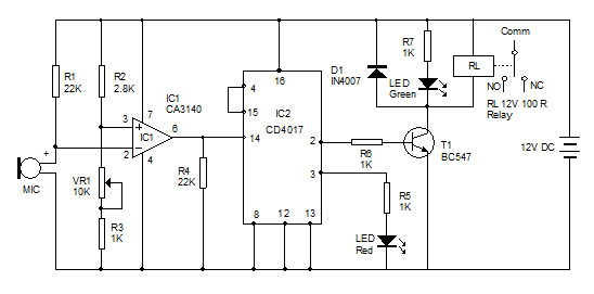
DIAGRAM Voice Operated Switch Circuit Diagram 1.Just sound of clapping[the sound of striking your palms together]. 2.Use coil pins of relay,a transistor and a diode. [I also, designed a very practical sound switch with a relay that work very good.]. Have a nice day, A tutorial on How to make a Clap Switch circuit aka Sound Triggered LED, along with detailed explanation on how the circuit works. The sensitivity or Range u The Circuit. An electret microphone is a type of condenser (capacitor) based microphone that converts sound energy to electrical energy. It is a low cost microphone that can be found in every cellphone, laptop, camera, and so on. The main component of the circuit is the electret microphone and it is used as the sound sensor.
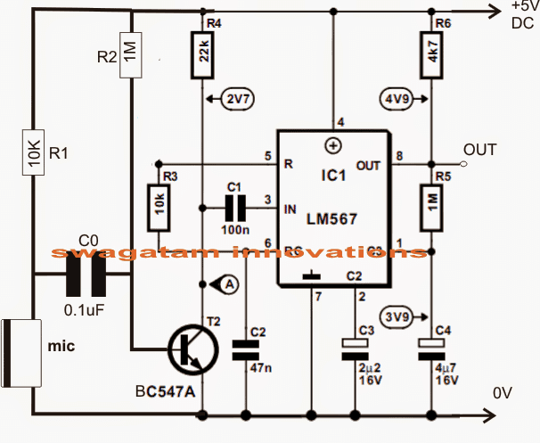
Sound Activated Timer Switch Code Since the Grove Sound Sensor produces a varying voltage, we can use the microcontroller's analog-to-digital converter (ADC) to handle that voltage. So, here is a simple Seeeduino Sketch, also compatible with Arduino Uno/Nano, that reads the voltage from the sound sensor module connected to A0 which is then Whistle activated light switch circuit with PCB. Surprisingly much, can turn on - shut down electric devices with a whistling sound. This is simple sound control circuit as the Whistle activated light switch circuit, that different from a little common circuit is requires high-frequency noise Such as whistle sound etc. Full circuit diagram and parts list can be found here: https://www.homemade-circuits.com/simplest-sound-activated-relay-switch/The video shows the test resul
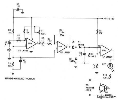
Sound Activated Switch Using LM386 & PC817 Circuit Diagram
This circuit is operating on 9-12V DC. The working of this circuit is quite simple, the main component is an audio amplifier LM386 IC. Following are the steps that you should follow to make this circuit work, Sound is received by an Electret mic which converts these sound signals into electrical signals.

The straightforward sound operated switch circuit demonstrated here will probably work at a distance of up to around 2 or 3 metres from a voice of average volume (slightly-less in case the xtal microphone insert is substituted with a medium or high impedance powerful sort). These two stages depend on Q1 and Q2 and work with a simple